Military Connector Miniaturization
Reply
The ideal goal of a DC/DC step-down (buck) point-of-load power module is to integrate the entire bill of materials (BOM) inside the package. In reality, most power modules require several external components, including input and output capacitors. These capacitors are usually external because they are too expensive and bulky to integrate in the package.
A high-switching-frequency buck architecture will minimize both the size and amount of external capacitors. But while these architectures shrink the BOM to enable integration in the module, you will have to make trade-offs in performance and operating range.
Take for example the TPSM84A21, a 10A DC/DC power module that uses a high-frequency two-phase architecture and switches at 4MHz. The TPSM84A21integrates 66.1µF of input capacitance and 185µF of output capacitance, a regulator IC, two inductors, and passives in a 9mm-by-15mm-by-2.3mm package. The only external component required is a single programming resistor. For comparison, the LMZ31710 is a 10A DC/DC power module in a 10mm-by-10mm-by-4.3mm package that switches at 500kHz and requires significantly more capacitance than the TPSM84A21, all external to the module. Table 1 compares the capacitance.
|
TPSM84A21 |
LMZ31710 |
|
| Input capacitance |
Internal: 66.1µF ceramic |
External: 100µF tantalum 47.1µ ceramic |
| Output capacitance |
Internal: 185µF |
External: 200µF tantalum 220µF ceramic |
Table 1: Capacitance comparison between the TPSM84A21 and LMZ31710
Let’s take a further look at how these two solutions compare in specs, solution size, efficiency, transient response and electromagnetic interference (EMI) performance.
Spec and feature comparison
The TPSM84A21 output range is from 0.55V to 1.2V. The TPSM84A22 is required for output voltages from 1.2V to 2.05V. In comparison as seen in Table 2, the LMZ31710 input range is wider and covers output voltages from 0.6V to 3.6V with a single device.
|
TPSM84A21 |
LMZ31710 |
|
| Minimum input voltage (V) |
8V |
4.5V |
| Maximum input voltage (V) |
14V |
17V |
| Minimum output voltage (V) |
0.55V |
0.6V |
| Maximum output voltage (V) |
1.35V |
3.6V |
| Maximum output current (A) |
10A |
10A |
| Typical switching frequency |
4MHz |
500kHz |
| Power good |
Y |
Y |
| Adjustable soft start |
N |
Y |
| Current sharing |
N |
Y |
| Adjustable current limit |
Y |
Y |
| Frequency synchronous input |
Y |
Y |
| Frequency synchronous output |
N |
Y |
Table 2: TPSM84A21 and LMZ31710 spec and feature comparison
Solution size
Figure 1 shows that although the TPSM84A21 package is larger, the overall solution area is 60% smaller.
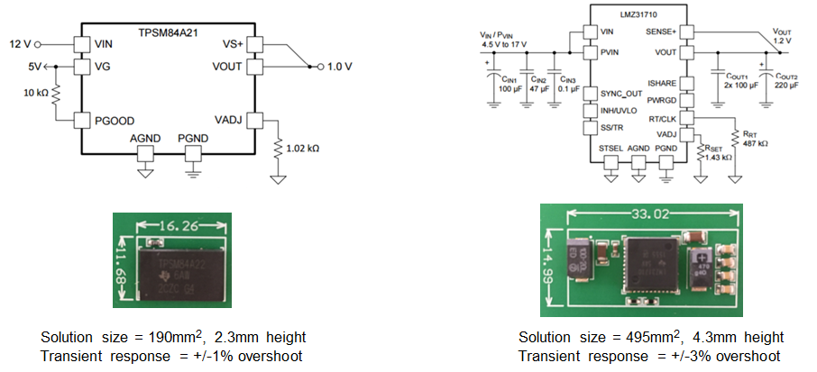
Figure 1: Solution-size comparison
Efficiency
Figure 2 shows that the efficiency of the LMZ31710 is much greater at low to mid loads; however, at full load the efficiency is similar to a 12V-to-1.2V conversion.

Figure 2: Efficiency comparison for a 12V-to-1.2V conversion
Figure 3 shows how the efficiency of the TPSM84A22 and LMZ31710 are similar for a 12V-to-1.8V conversion.
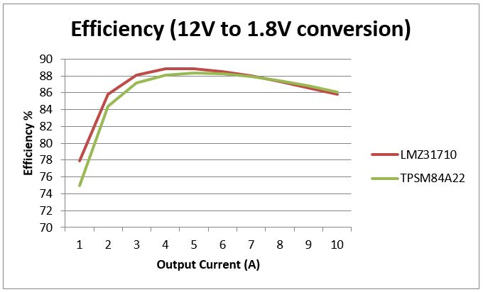
Figure 3: Efficiency comparison for a 12V-to-1.8V conversion
Transient response
As you can see in Figure 4, the TPSM84A21’s transient response is considerably better in a worse-case condition, with no external output capacitance.
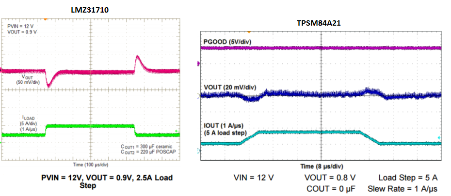
Figure 4: Transient response comparison
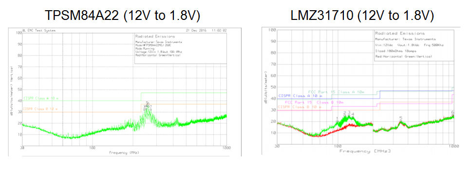
Radiated EMI
In Figure 5, the radiated EMI of both the TPSM84A22 and LMZ31710 meet Comité International Spécial des Perturbations Radioélectriques (CISPR) 22 Class B radiated EMI, but the LMZ31710 has lower peak emissions.
Figure 5: Radiated EMI comparison
Conclusion
Integrating the input and output capacitors in a small footprint requires a high-switching-frequency architecture, which significantly reduces the overall solution size and transient response and makes the design incredibly simple. The trade-off is a narrower operating input and output voltage range, lower efficiency in some conditions, and higher peak-radiated EMI. With a traditional current-mode buck architecture, the operating range is wider, offering good efficiency and more features. Depending on the situation, both the TPSM84A21/2 and LMZ31710 are excellent options for point-of-load applications.
Need Immediate Assistance?Call Toll Free 1-888-257-5027 or email us: sales@nusourcetech.com
 Analog Devices HMC8108 Low Noise Converters Analog Devices HMC8108 Low Noise Converters are offered as compact, X-band, gallium arsenide (GaAs), monolithic microwave integrated circuit (MMIC) in-phase/quadrature (I/Q) converters. The HMC8108 series converts 9GHz to 10GHz radio frequency (RF) input signals to a typical 60MHz single-ended intermediate frequency (IF) signal at its output. The HMC8108 Converters deliver a small signal conversion gain of 13dB with a noise figure of 2dB. The converters also have 20dBc image rejection. The HMC8108 Converters are designed with a low noise amplifier followed by an image reject mixer. The image reject mixer eliminates the need for a filter following the low noise amplifier and removes thermal noise at the image frequency. I/Q mixer outputs are provided, and an external 90° hybrid is needed to select the required sideband. Compatible with surface-mount manufacturing techniques, the HMC8108 converters serve as a much smaller alternative to hybrid style, image reject mixer, down converter assemblies. |
|
Features
Applications
|
Block Diagram |
Analog Devices EVAL-HMC8108 Evaluation BoardAnalog Devices EVAL-HMC8108 Evaluation Board helps designers evaluate the features of the 9GHz to 10GHz HMC8108 Low Noise Converters. Developed using RF circuit design techniques, the board provides a sufficient number of via holes to connect the top and bottom ground planes. Signal lines with 50Ω impedance connect the package ground leads and exposed pad directly to the ground plane. |
Need Immediate Assistance?Call Toll Free 1-888-257-5027 or email us: sales@nusourcetech.com
Historically, the DRAM market has been the most volatile of the major IC product segments. Figure 1 reinforces that statement by showing that the average selling price (ASP) for DRAM has more than doubled in just one year. In fact, the September Update to The McClean Report will discuss IC Insights’ forecast that the 2017 price per bit of DRAM will register a greater than 40% jump, its largest annual increase ever!
Just one year ago, DRAM buyers took full advantage of the oversupply (excess capacity) portion of the cycle and negotiated the lowest price possible with the DRAM manufacturers, regardless of whether the DRAM suppliers lost money on the deal. Now, with tight capacity in the market, DRAM suppliers are getting their “payback” and charging whatever the market will bear, regardless of whether the price increases hurt the users’ electronic system sales or causes it to lose money.

Figure 1
The three remaining major DRAM suppliers—Samsung, SK Hynix, and Micron—are each currently enjoying record profits from their memory sales. For example, Micron reported net income of $1.65 billion on $5.57 billion in sales—a 30% profit margin—in its fiscal 3Q17 (ending in May 2017). In contrast, the company lost $170 million in its fiscal 4Q16 (ending August 2016). A similar turnaround has occurred at SK Hynix. In 2Q17, SK Hynix had a net profit of $2.19 billion on sales of $5.94 billion—a 37% profit margin. In contrast, SK Hynix had a net profit of only $246 million on $3.39 billion in sales one year ago in 2Q16.
Previously, when DRAM capacity was tight and suppliers were enjoying record profits, one or more suppliers eventually would break rank and begin adding additional DRAM capacity to capture additional sales and marketshare. At that time, there were six, eight, or a dozen DRAM suppliers. If the supplier was equipping an existing fab shell, new capacity could be brought on-line relatively quickly (i.e., six months). A greenfield wafer fab—one constructed on a new site—took about two years to reach high-volume production. Will the same situation play out with only three DRAM suppliers left to serve the market?
Recently, Micron stated that it does not intend to add DRAM wafer capacity in the foreseeable future. Instead, it will attempt to increase its DRAM output by reducing feature size that, in turn, reduces die size. Eventually, as the company moves down the learning curve, it will be able to ship an increasing number of good die per wafer. However, SK Hynix, in its 2Q17 financial analyst conference call, stated that it plans to begin adding DRAM wafer capacity since it is not able to meet increasing demand by technology advancements alone. Samsung has been less forthcoming in its plans for future DRAM production capacity.
Although Samsung and Micron may tolerate SK Hynix’s DRAM expansion efforts for a short while, IC Insights believes that both companies will eventually step up and add DRAM wafer start capacity to protect their marketshare—and DRAM ASPs will begin to fall. As the old saying goes, it only takes two companies to engage in a price war—and there are still three major DRAM suppliers left.
Need Immediate Assistance?Call Toll Free 1-888-257-5027 or email us: sales@nusourcetech.com
UL 94 V-0 low flammability rated optical fiber for industrial and telecommunications networks
“Strong, durable Molex Polymicro FR Fibers meet industry requirements for flammability protection.”
“Having a fiber with a low flammability buffer coating offers a distinct advantage in applications where enhanced flammability protection is of paramount importance,” said Jim Clarkin, Polymicro general manager, Molex. “Strong, durable Molex Polymicro FR Fibers meet industry requirements for flammability protection.”
Polymicro FR Optical Fibers are available in telecommunications grade singlemode or 50µm and 62.5µm graded index construction with a 125µm glass OD/250µm buffer OD. Designed for superior dimensional control and tight tolerances, Polymicro FR Optical Fibers have an operational temperature range of -40 to +100°C. The UL 94 V-0 flammability rating indicates characteristics recommended in applications requiring increased protection from flame propagation and combustion.
The buffer utilized in Polymicro FR Optical Fiber is mechanically strippable similar to an acrylate buffer and imparts exceptional fiber strength. Molex can provide multiple size fibers and buffers, including multimode step index constructions. Available as single fiber in a variety of jacketing materials, Polymicro FR Optical Fibers range from less than 50 microns to over 600 microns in core diameter.
Molex vertically integrated manufacturing capabilities enable production of a complete range of optical fibers designed for deep-UV, NIR and broad-spectrum applications. Polymicro Optical Fiber assembly design configurations are highly customizable, incorporating optomechanical and electromechanical components with custom configured fused silica, in addition to advanced optical features including micro-machined end tips, metal terminations or precision couplings. Fiber type, termination style and jacketing can be specified for optimal application alignment and system performance.
“Molex customer design requirements vary widely in complexity—from a single, finished optical fiber to a complex branching assembly. Our expanding range of Molex Polymicro Optical Fiber profiles and custom assemblies give customers the design flexibility they need for demanding applications, environmental conditions and optical wavelengths,” adds Clarkin.
For more information about Polymicro FR Optical Fiber please visit www.molex.com/polymicro/opticalfibers.html.
About Molex:
Molex brings together innovation and technology to deliver electronic solutions to customers worldwide. With a presence in more than 40 countries, Molex offers a full suite of solutions and services for many markets, including data communications, consumer electronics, industrial, medical, automotive and commercial vehicle. For more information, please visit www.molex.com
Need Immediate Assistance?Call Toll Free 1-888-257-5027 or email us: sales@nusourcetech.com